


Introduction…
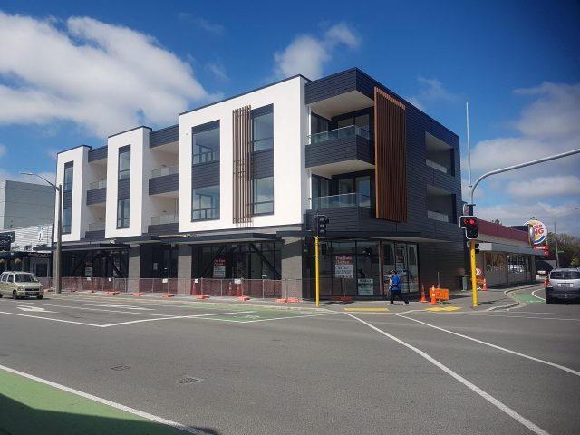
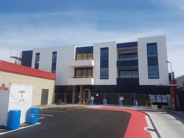
Transparency was engaged by Christchurch Property Projects (the Client) to provide Structural Design & Construction Monitoring services for the now nearly completed (as of early January 2020) three-level High Street Building in Rangiora…
Transparency completed the Structural Design of both the Foundation and Superstructure including Cold Case for Cross Laminated Timber (CLT) elements and Cold & Hot Cases for Steel elements with PTL engaged by the Client to complete the Hot Case for CLT elements…
Transparency has been completing the Construction Monitoring for the abovementioned design work under our responsibility to a CM3 standard as requested by council…
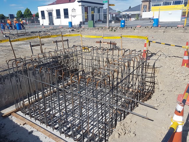
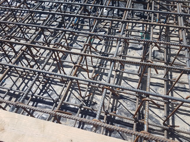
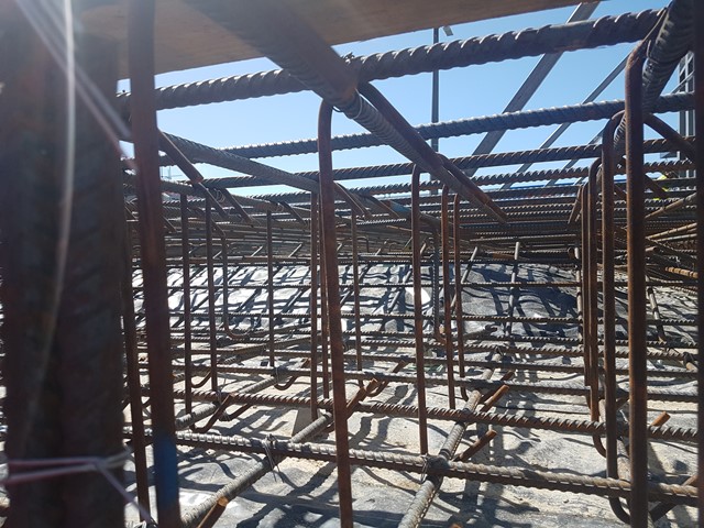
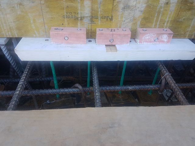
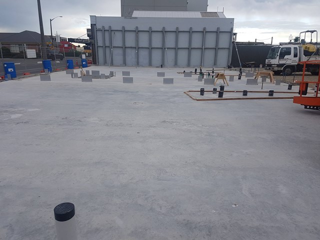
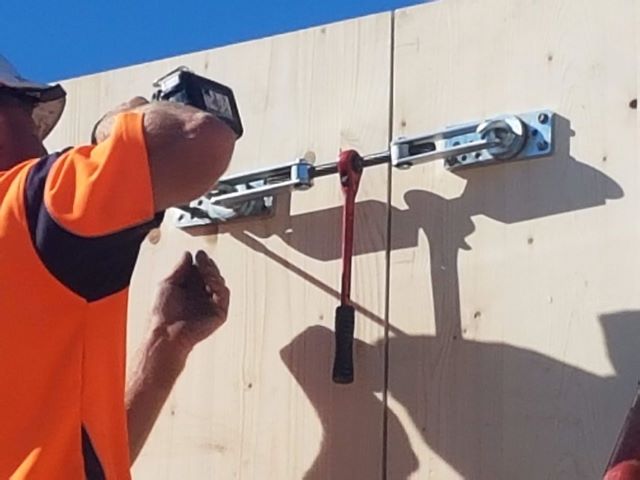
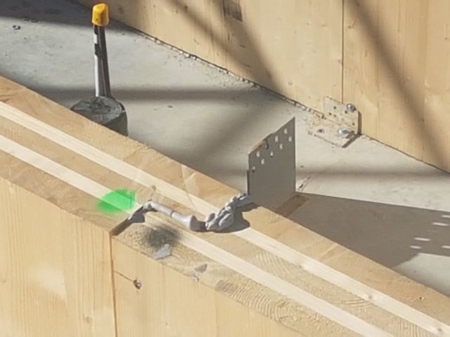
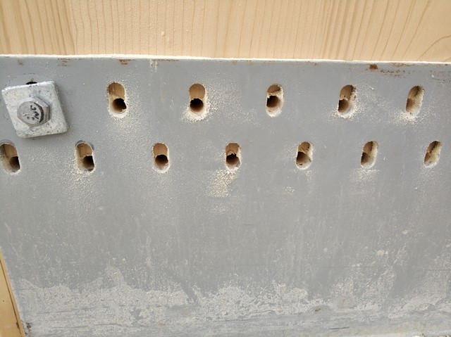
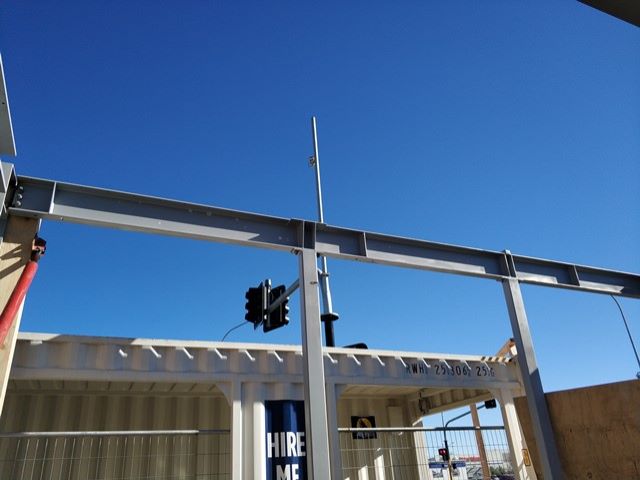
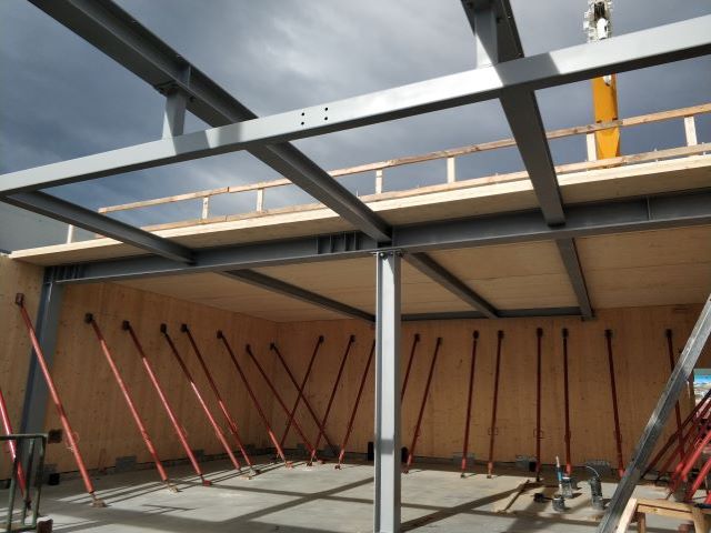
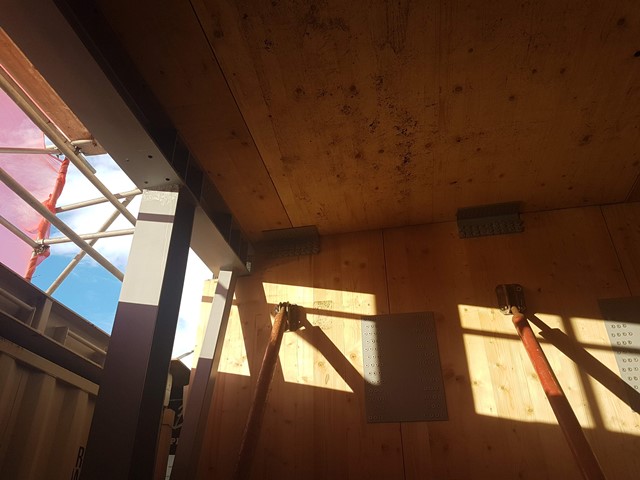
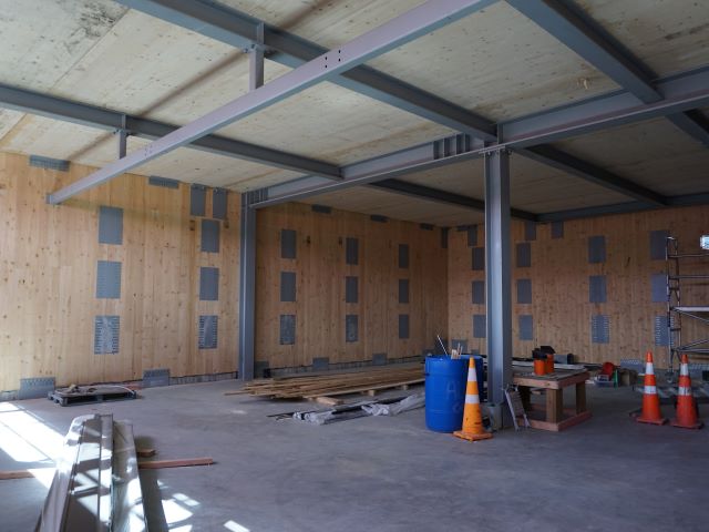
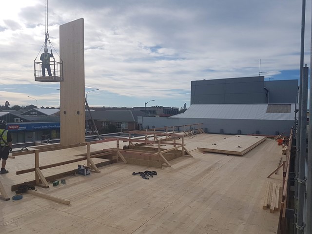
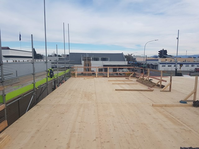
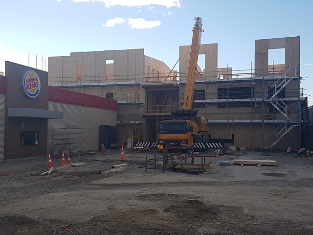
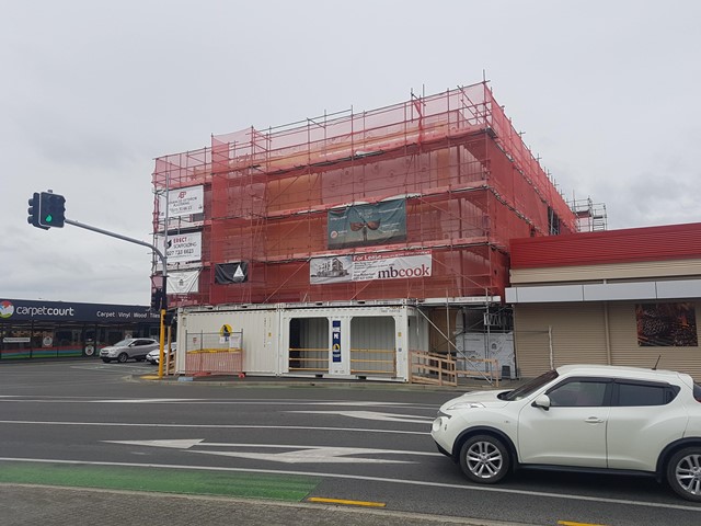
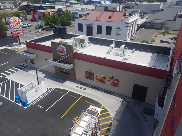
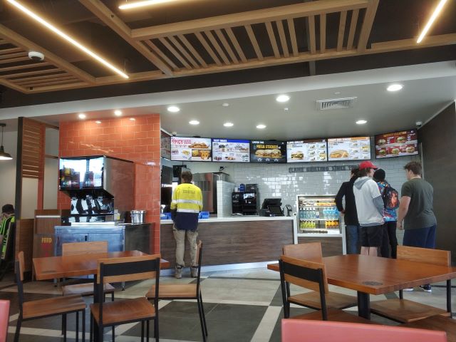
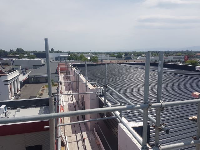
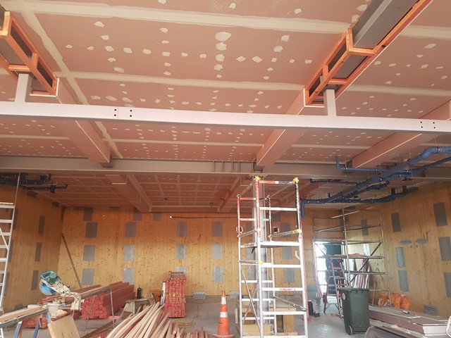
We felt to write this article (including the above galley of ‘work in progress’ photos showing construction development to date) to highlight key aspects of the journey, from the initial Client engagement, clarification of the intended scope, adjacent on-site construction considerations (as there were two other building projects which Transparency also provided Structural Design & Construction Monitoring services for, to the Client, immediately adjacent to 39-49 High Street), selection of structural materials, design challenges overcome, shop drawing review, temporary construction loading conditions, minor on-site remedial fixes and finally, learnings (hindsight is 20/20) and continuous improvement opportunities… 🙂
Initial Client Engagement / Clarification of Intended Scope…
Transparency was engaged to provide preliminary concept Structural Design services for either a potential three-level or four-level mixed-use retail, office and apartment building whilst the Client sought the market in terms of which of the two options would be more commercially feasible given that it would become Rangiora’s first inner-city apartment building…
After initial costings (by Contract Construction) and market research (by local real estate agents) were completed, the design team was informed by the Client that we’d be designing a three-level building with ground-floor retail tenancies and upper floor apartment units (i.e. no upper floor office tenancies)…
Adjacent On-site Construction Considerations…
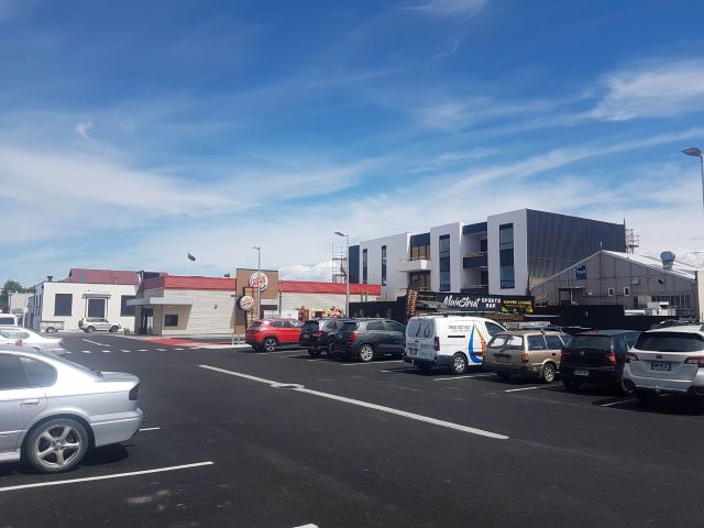
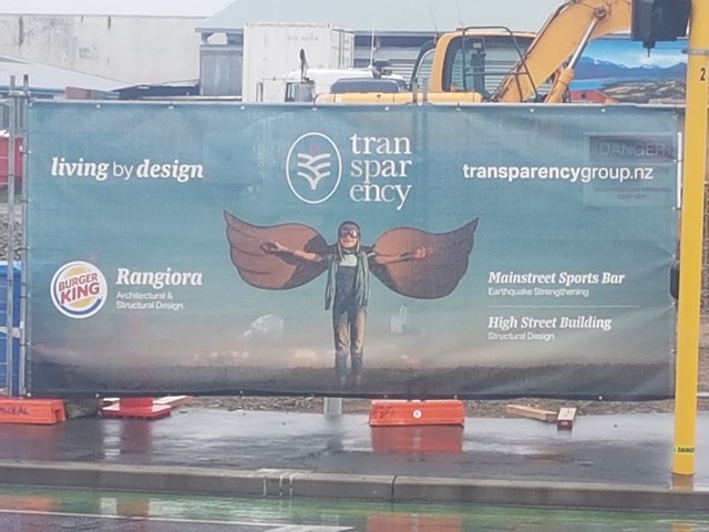
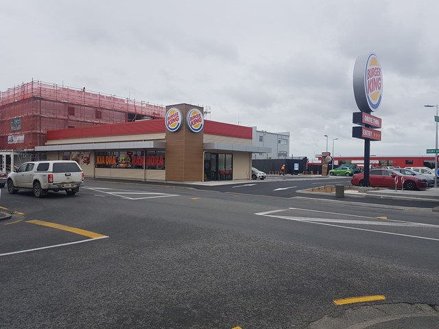
Burger King Rangiora was to be built along the Ivory Street frontage immediately adjacent to High Street Building with approximately 2m between (with this space to be utilized for storage by Burger King) to the South…
Main Street Sports Bar was in need of earthquake strengthening (up to 70% NBS) and was sitting on the existing 37 High Street boundary to the East of 39-49 High Street…
Both sites (Burger King Rangiora & Main Street Sports Bar) were also owned by the Client (and were concurrently being designed & strengthened by Transparency), along with 39-49 High Street, under various titles…
After completing an appraisal of the existing layout of the Main Street Sports Bar including engaging Concrete Structure Investigation to complete Concrete Scanning services to indicate the existing reinforcing within the various concrete elements in the building, along with receiving confirmation from council that an easement could be legally provided between 37 and 39 High Street, it was concluded by Transparency (after first being suggested by Contract Construction) that it would be most prudent to endeavour to provide the majority of the structural strengthening system required for Main Street Sports Bar externally to the reinforced concrete West Elevation wall of the building…
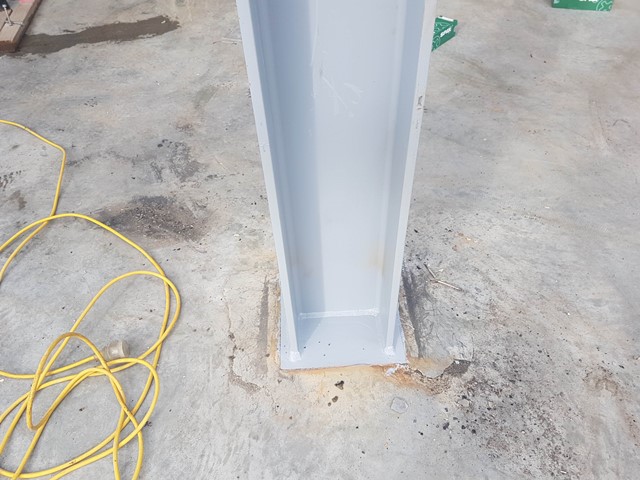
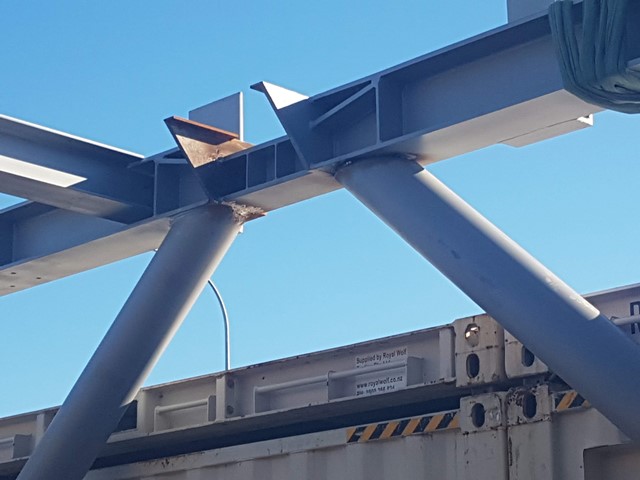
In the East-West direction the walls, mezzanine and roof were all tied back to and bolted through the West Elevation wall onto a solid welded steel frame with vertically cantilevering columns which were then provided with a full moment fixity welded detail to an extension of the reinforced concrete foundation for High Street Building which was poured right up to the existing foundation of 37 High Street…
A suitably sized gap was provided between Main Street Sports Bar and High Street Building to ensure that impact loading between the two systems did not occur during an East-West ULS seismic event…
Selection of Structural Materials…
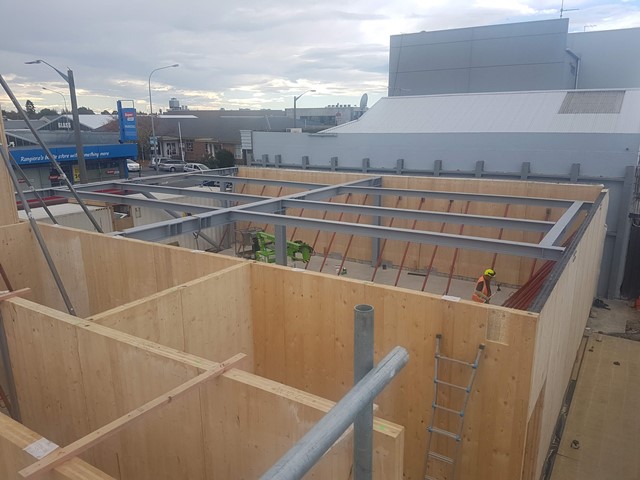
Due to the above boundary conditions and also Burger King Rangiora’s desire to achieve the removal of the scaffolding for the South Elevation of High Street Building by the time it opened for business, it was decided to utilize CLT wall, lintel and floor panels (all 150 thick with 5 layers 40-30-20-30-40) in as many places as possible in the build…
This was considered to provide the quickest and lightest (from a crane positioning and reach perspective) structural system which would also reduce load demands on the foundation…
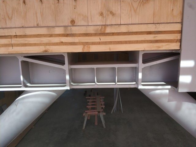
Due to the shopfront glazing along the High Street frontage and ‘open’ nature of the ground floor tenancies in the East-West direction, hot-rolled steel frames were engaged both along the North Elevation shopfront and also centrally…
Wherever possible the CLT wall and lintel panels (along with their associated connections) provided full static (gravity and live load) and dynamic (wind and earthquake load) resistance in the Cold Case…
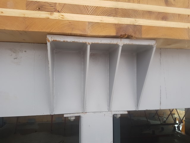
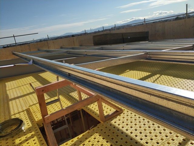
As an example of this, the secondary precambered hot-rolled steel beams supporting the 1st and 2nd floor CLT floor panels were all bolted to (i.e. through) the CLT wall panels where there were CLT wall panels present to connect to…
Design Challenges Overcome…
The Client’s selected local CLT supplier sourced the 12,000 length x 2,350 width CLT panels from HNT in Austria, as billets which were shipped in 40-foot containers to New Zealand…
As the floor to floor heights required by Threefold Architecture all exceeded the available 2,350 width, we were not able to endeavour to align the wall panels lengthwise and thus needed to assess aligning them width-wise…
We commenced by considering Balloon Construction, where all the full-height CLT wall panels would have been erected first before the CLT floor panels, but as we had internal full-height CLT wall panels also, the temporary propping of these wall panels appeared to us to be inhibitive with respect to subsequently being able to instal the CLT floor panels onto their required corbels, so we parked that approach…
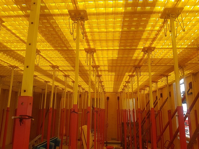
That only left us with the Platform Construction option of piecemeal CLT wall panels up to the underside of the next CLT floor panels, which is the option we subsequently pursued…
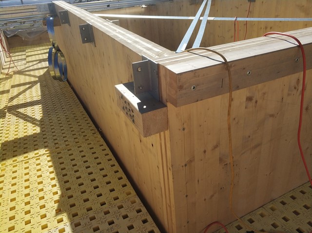
This Platform Construction option allowed ease of erection of all the CLT wall panels for a level (with all the panels being light and easy to manoeuvre), temporary propping and then (once all secondary steel beams and other steelwork was in place) the easy installation of the CLT floor panels directly above…
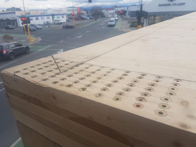
As an aside, in some high load hold down (push-pull) locations at the ends of stitched CLT wall panels the crushing load (perpendicular to the grain) imposed on the CLT floor panels exceeded capacity so we needed to locally provide full CLT floor panel depth compression reinforcement (in the form of closely spaced fully threaded SPAX screws) to assist the transfer of forces through the CLT floor panels and down into the CLT wall panel below…
Once the methodology of how the CLT wall panels would be handled was decided, the next major design challenge was how the earthquake forces were to be resisted…
In the East-West direction, the resistance was shared between the North and South Elevations with no internal walls at ground floor level (only above supported on the centrally located hot-rolled steel gravity frames) which meant that the 1st floor CLT floor diaphragm needed to transfer lateral loads from these 1st and 2nd floor CLT walls to the South and North Elevation systems (we also de-coupled selected CLT wall panels in both earthquake directions to better match the required stiffnesses so that we could limit the amount of lateral earthquake load resisted by various overall walls)…
The North Elevation was the shopfront and we needed to employ ductile (mu=3) EBF’s with active links and suggested to the Architectural Designer an arrangement of these (especially their diagonals) which would enable entrances to the ground floor tenancies, lift shaft and stairs…
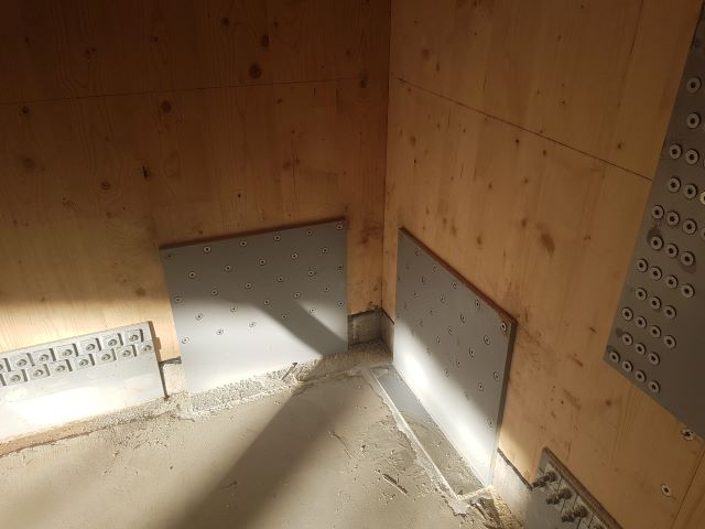
The South Elevation consisted of CLT wall panels and we also provided these with ductility (mu=3) at connection-to-foundation-level only (utilizing the debonded length of various G300E deformed hold down bars embedded in the foundation) and provided overstrength (to avoid brittle failure modes) to all the CLT wall panel connections…
We needed to endeavour to balance the inelastic lateral deflections between the South and North Elevations (which was complex due to the dissimilar structural materials involved) and tweak the active link design of the EBF’s accordingly (which gave us some fine-tuning capabilities)…
We wanted to achieve this to avoid placing excessive racking or skew loading onto the 1st and 2nd floor CLT floor diaphragms…
To achieve an understanding of how the earthquake loads were being transferred (not just the lateral loads but also the effect of the gravity and live loads) to the CLT wall panels we concocted a spreadsheet to work out these actions (overall wall by wall) at each level which we were then able to assign individual overstrength factors to (again overall wall by wall)…
Obviously, tweaks and changes which were required along the way were iterative and affected other CLT wall panels so the spreadsheet was regularly updated…
For the analysis of the EBF’s (along with their active links) and gravity hot-rolled steel frames, we used Microstran and the NZS 3404 design module…
Once the earthquake loadings were quantified for each CLT wall panel from the spreadsheet and the various overall wall overstrength factors were applied, we utilized the Pro:Holz CLT Design Guide, the FP Innovations CLT Handbook by the Canadian Wood Council, Eurocode 5 (as NZS 3603 doesn’t presently include any provisions for CLT design), the HNT ETA* and the SPAX ETA* (*European Technical Approval) to complete the various member and connection designs…
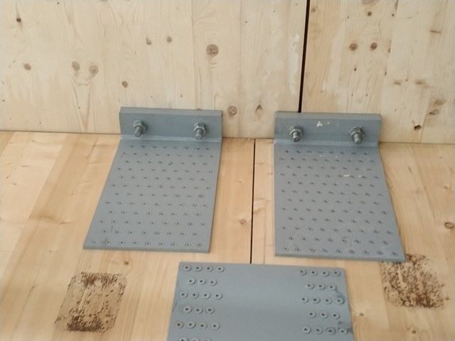
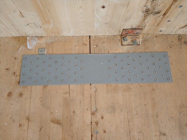
Another key principle which we needed to consider, was to provide vertically slotted holes to the shear connector plates resisting horizontal shear forces in CLT wall panels from lateral earthquake loading, which allowed them autonomy from the inter-related hold-down connections…
Shop Drawing Review…
The Client’s selected local CLT supplier provided the CLT wall, lintel and floor panel Shop Drawings and iDetail provided the Structural Steel Shop Drawings based on Transparency’s Structural Drawings…
We had clear back-and-forth communication with both parties and after thorough reviews, we provided our ‘no structural objection’ responses…
Temporary Construction Loading Conditions…
When construction reached the stage where all the CLT wall, lintel and floor panels were in place (along with the roof being in place) but only some external glazing was in place, Contract Construction noticed during a wind gust event that the bare (unloaded) CLT floors were vibrating up and down on their secondary hot-rolled steel beams…
Transparency did not observe this occurrence ourselves but concluded that the remaining openings must have made the (under-construction) building behave like a building with a dominant opening in the windward wall, i.e. filling up with air with nowhere to go (as the majority of the installed windows and sliding doors to the external building envelope would have been closed) which excited the secondary beams supporting the CLT floor panels in vibration…
The approach to mitigate this effect during construction would be to endeavour to install glazing to the predominant wind direction on-site first or, if this was not achievable, to ensure that any windows or sliding doors installed be left open until all windows and sliding doors were in place, at which time all would be kept closed…
Internal plasterboard linings are traditionally stacked on inter-storey floors before being fixed in place thus Transparency provided the Contractor with a limit to the number of sheets of plasterboard they could place on top of each other…
Minor On-site Remedial Fixes…
There was one instance where a half lap was provided, to a CLT wall panel edge butting up next to the lift shaft CLT wall panels, where it wasn’t required but as this was not in a critical location, i.e. we weren’t utilizing that panel for lateral load resistance, solid continuous CLT blocking was provided up this panel edge…
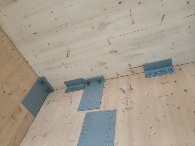
There was one other place where a steel chord plate (connecting the CLT floor panels ensuring their diaphragm action) was in a conflicting location on top of the floor panels and so we placed it underneath the floor panels but needed to weld it to either side of the top flange of one of our hot-rolled steel secondary beams…
We also provided a remedial detail with respect to the fixing of the roof bracing, where, in certain locations from a practical perspective we needed a wider surface to connect the required bracing to than we had initially provided…
Learnings and Continuous Improvement Opportunities…
For a project which didn’t require a clear CLT wall panel height exceeding 3.5m between CLT floor panels, we discovered that German CLT manufacturer Binderholz offer up to 20,000 length x 3,500 width CLT panels (these would need to be cut down to 12,000 lengths for transportation in 40-foot open-top containers) which could be turned on their side to enable long squat wall panels (which would remove the need to provide stitch plates and individual shear plates)…
High Street Development had two floor-to-floor heights where the clear CLT wall panel height was in excess of 3.5m so this wouldn’t have been an option…
Binderholz provides CLT panels with very similar structural properties to that of HNT (both of which offering around twice the strength and stiffness of that then provided by equivalent thickness CLT panels manufactured from local radiata pine)…
Limiting the number of panels required and thus connections required would be a big positive in terms of both construction time and maximizing the construction team’s enjoyment of the construction process (and also in reducing the potential for clashes during the design process)…
Another avenue for learning for Transparency would be to investigate the suitability of proprietary pre-manufactured bracketry (utilized in Europe) for use in subsequent projects (keeping in mind that earthquake loading is not a dominant design consideration in Europe)…
Unless you had a site where the building wasn’t anywhere near the boundaries and which also didn’t have any internal CLT wall panels, Balloon Construction wouldn’t be feasible (due to internal temporary propping requirements) so we would opt to continue utilizing Platform Construction in subsequent CLT buildings…
Appreciation…
We hope you’ve enjoyed viewing the above photos and (maybe even) reading this article…
We appreciate your time and interest… 🙂